Let's have a look on the design of the getting started tutorial once again. If you have not made the design of the getting started so far, you should go back and do the getting started first (Getting Started). So far, the only adaptation we made were the parameter names. Now, we want to adapt the applet to process images from cameras with the following properties
- image side size 512 x 512
- 12 bit / pixel grayscale
- Camera Link interface in dual tap base configuration mode
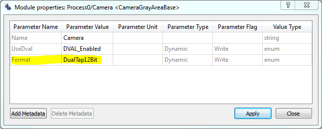
Our design is already equipped with a CameraGrayAreaBase operator. This operator is from the mE4VD4-CL operator library and is only available for mE4 Camera Link frame grabbers, i.e., the mE4VD4-CL library is a library containing hardware specific operators. The CameraGrayAreaBase operator supports grayscale area scan cameras using Camera Link in base configuration mode. Double click on the camera module in your design to open it's properties. One of the parameters is called "Format". Here, the specific Camera Link format can be selected. We select DualTap12Bit, apply our changes and close the window. Our design is now capable to acquire 12 bit camera images.
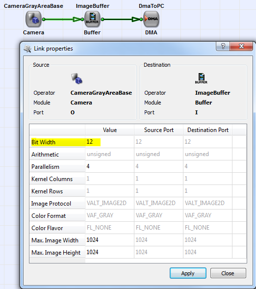
Note that the "Format" parameter is dynamic. This means, the value can be changed after synthesis of your design in hardware which allows the flexible use of multiple camera formats. However, if we double click on the link at the camera, we see that the link's bit width is still at 8 bit/pixel. Moreover, the maximum image dimension is not large enough. You might ask yourself why a 12 bit camera can be used if the link only has 8 bits. The answer is that only to eight most significant bits of the camera images are transported i.e. only the available link bits are used. The operator will automatically select the correct bits from the images depending on the settings in the camera operator. Check the documentation of the camera operators for more information ('CameraGrayAreaBase'). We will change the bit width to 12 bit to process the full camera bit depth.
After changing the value, click on Apply. As you can see, the color of the links between the camera, the buffer and the DMA has changed from black to green. This indicates that the change was accepted and validated. Moreover the link property "bit width" was propagated through the image buffer to the link between the buffer and the DMA module. Thus, users are not required to change the bitwidth on every link. Link properties are propagated through modules until they change the link bitwidth themselves or require user input. If you open the link properties of the link between the buffer and the DMA, you will notice that it is not possible to change the bitwidth here.
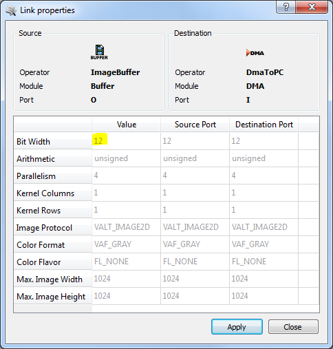
That's because the antecedent operator ImageBuffer is not capable to change the link bit width. Hence, link properties can only be changed if the connected operator allows the change i.e. is by definition an operation which influences the bit width.
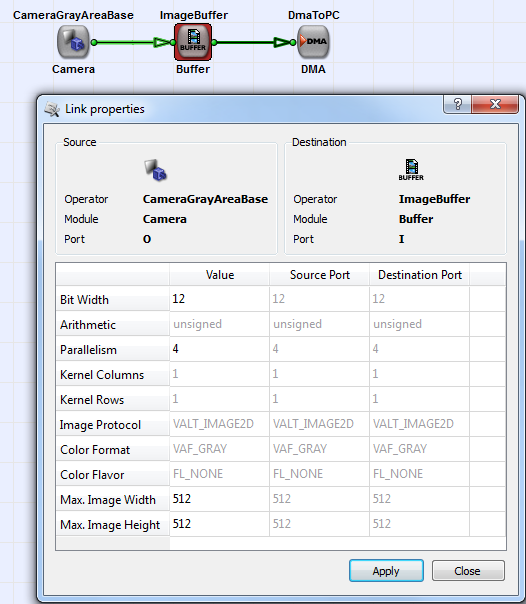
The required image side size for the camera is 512 x 512 pixel. In the link properties, we can see properties called Max. Img Width and Max. Image Height. These properties represent the maximum image dimension on the link. This is the maximum. Any lower dimensions are allowed. However, an image size exceeding this limitation will violate the VisualApplets design rules and you might get an error when using the applet in hardware.
The setting of the image dimension should always be chosen to the required minimum as a lower image dimension can save FPGA logic and memory resources. Back to our example: Open the link properties of the link between the camera and the buffer and select a maximum image width and height of 512 x 512. After you are done, click on apply.
Again, you will notice that the change directly influenced the link properties of the current link and the link located after the buffer module. Moreover, you can see that the buffer module is now marked red. That's because we now have created a so called "illegal condition". This means, one or more of the link properties are not compatible with the parameter settings in the module. In our case, the parameter settings of the ImageBuffer cannot be used with the settings of the link. If you close all property windows and perform a design rules check Ctrl+F7 you will get error messages as shown in the following figure.
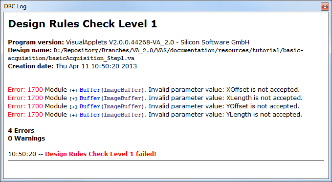
You can click on one of the error messages to highlight the module with the error. This is very useful if you have large designs in multiple hierarchies and cannot immediately see where the operator is located. Now, open the properties dialog of the Buffer module. Again, you can see that the four parameters which cause the error are dyed in red.
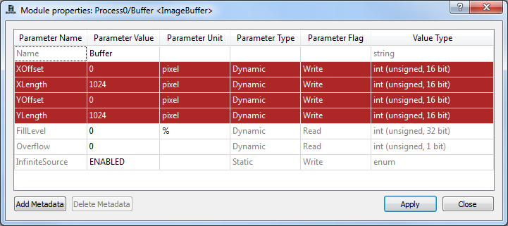
Also, the reason for the error now becomes obvious: A region of interest in the operator is set which is larger than the maximum allowed image dimension on the link. This will violate the operator's parameter range and the VisualApplets design rules and therefore, causes the error. You can immediately bring your design into a valid condition by changing the XLength and YLength parameters to value 512.
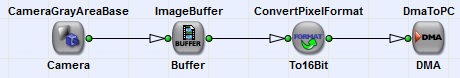
We are almost done with our design. We can already start the build and use the design in hardware. However, there is one more step we should consider. So far, we connected our 12 bit pixel values directly to the DMA module. This will cause the transfer of 12 bit for each pixel to the PC. This format is very difficult to be handled by software programs as pixels are distributed to multiple bytes. Therefore, each pixel should consume exactly one or more byte. In our example, we expand our pixel to 16 bit. To do so, we need to place another operator between the buffer and the DMA module. There exists several operators to solve our task. We will use operator ConvertPixelFormat from the base operator library. Place the operator between the buffer and the DMA module. If you place the operator directly over the link, the operator will automatically be inserted. Next, you should rename the module to "To16Bit" and open the link properties behind the operator. As you can see, the default link bit width is chosen for the module output which is 8 bit per pixel. Thus, the module has overwritten the input link bit width. Any changes of the input link bit width are ignored. The module will always output the parameterized value. The default eight bit per pixel will decrease the bit width from 12 to 8, but instead, we want to increase the bit width. So, you just need to change the link property value to 16 bit and confirm the changes.
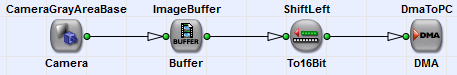
The ConvertPixelFormat operator will now expand the 12 bit input pixels to 16 bit by inserting four constant zero-bits at lower positions. In other words, we performed a left shift by four bit. Instead of using the ConvertPixelFormat operator, operator ShiftLeft can be used in alternative. Delete the ConvertPixelFormat operator from you design by selecting it with the mouse and press delete from the pop-up menu or from the main menu bar; or simply press Del . Insert operator ShiftLeft from the arith operator library. Insert it into the design and check the link properties. As you can see, the link bit width is still at 12 bit and cannot be changed in the link properties. For this operator, the link bit width is changed by a parameter. Namely parameter Shift. Change the parameter value to 4 and, apply the changes and go back to the link properties. As you can see, the link bit width has now been changed to 16 bit. To summarize: Some link properties can be changed on the link while some are changed using operator properties. In the respective example these two methods are required for the operators because one is used to specify the output bitwidth independent of the input bitwidth i.e. the shift value is automatically determined. While the shift operator is used to specify the shift value. Here, the output bitwidth is automatically determined by the parameterized value and the input bit width.
In the example, we inserted four bits at the lower bit position. If you rather want to add four bits to higher bit positions to get 16 bit you can use operator CastBitWidth instead.
An explanation and examples of the bit manipulation operators can be found in the operator reference. See 'ConvertPixelFormat', 'ShiftLeft', 'ShiftRight' and 'CastBitWidth'.
We now have finalized the extension of our basic acquisition design. Next, you can build and use your design in hardware. You have learned on how to set parameters and how to solve conflicts. In the next section, a list of the basic acquisition applets for all kind of cameras is given.
